| Group By:
|
The grouping list options are provided to display
pipe components in the table.
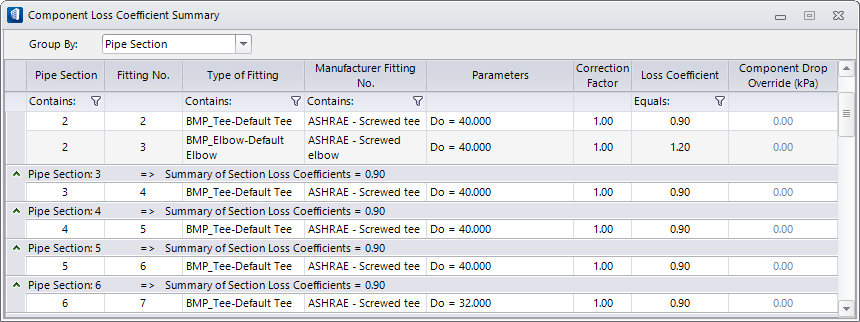
- Pipe Section —
Displays the pipe components grouped in sections in ascending order. The
collapse/expand arrow icons appears in the leftmost column. The summary row
above each section displays the sort criteria and the section number
(Pipe Section:#), where # indicates the section number.
The heading also displays
Summary of Section Loss Coefficients,
that is the sum of section loss coefficients of fittings in the section.
- Fitting No. —
Displays the pipe components grouped under fitting numbers in ascending order.
The collapse/expand arrow icon appears in the leftmost column applicable for
entire fitting number list. The summary row above the fittings list shows only
heading of the group by criteria (Fitting No.:#), #
being the identification number of fittings in sequence.
- Type of Fitting —
Displays the pipe components based on type of fittings. The table is sorted
based on Type of Fittings column in an alphanumeric order. The summary row
above the fittings list shows only heading of the group by criteria (Type of
Fitting: Name of Fitting), e.g. all default elbow fittings in entire pipe
system will be grouped under the summary head
Type of Fitting: BMP_Elbow-Default
Elbow.
- Manufacturer Fitting
No. — Displays the pipe components based on Fitting Codes assigned as per
manufacturer fitting nos. The table is sorted based on Manufacturer Fitting
No., column in an alphanumeric order. The summary row above the fittings list
shows only heading of the group by criteria (Manufacturer Fitting No.: Pipe
Fitting Code), e.g. all elbow fittings in entire pipe system will be grouped
under the summary head
Type of Fitting: Elbow-#.
Note: The
Manufacturer Fitting No. field is set through fittings database during sizing
analysis.
|
| Pipe Section
|
List the pipe section numbers. The section groups
are numbered in ascending order in the direction of flow.
|
| Fitting No.
|
A pipe section can have more than one fittings.
These fittings are numbered in order of direction of flow. The
numbers increment with sections.
|
| Type of Fitting
|
Lists the name of the fitting each against the pipe
section. Selecting a fitting in this column highlights corresponding piping
element in the geometry. The
opens a comment panel where you can write a comment
about the fitting. The commented cell is indicated with a blue triangular mark
in the top right. These comments are preserved in the system and are useful for
future reference These comments captured and are listed in a column in
applicable reports.
The filter icon below this field can be used to
filter the required fittings.
The "Contains:" field at
 icon is used to set a filter for
listing those Type of Fittings. icon is used to set a filter for
listing those Type of Fittings.
|
| Manufacturer Fitting No.
|
Lists the code of the fitting each against the pipe
section.
Sets the industry standards notations to duct
system fittings, for example fittings in ASHRAE standards, ED1-3, CD9-1, etc.
The convention is two letters followed by two digit numbers separated by a
hyphen.
Consider the example:
ER4-1
- The first letter
E denotes fitting function
Exhaust
or Return.
- The second letter
R denotes fitting geometry
Rectangular for a rectangular shape.
- The first digit
4 denotes fitting categoryTransitions.
- The second digit
1 denotes sequential number of such
fittings. (Number greater than 1, say 2 means the system has at least two such
category fittings already in use).
The "Contains:" field at
icon is used to set a filter to
list desired Manufacturer Fittings displayed in the dialog.
|
| Parameters
|
Populates calculation parameters for respective
fittings selected from the manufacturer fitting.
|
| Correction Factor
|
Displays the correction factor value. It is a
multiplier and set to default
1.00. For non-Standard fittings, setting it
to a different value, say 1.1 will compute loss by taking the correction of 10%
tolerance margin. This correction is allowed provided you adopt a right fitting
in the design, for example, using pipes with insulation layer. The revised loss
values for fittings will also reflect in the Section Summary table.
|
| Loss Coefficient
|
Displays the loss coefficient value for the pipe
fittings. Usually the standard values of fitting specification as provided by
the supplier. For manufacturer fittings, the standard values are picked from fittings
table database and are non alterable.
For
Group By: Section, the section wise
losses summed up for fittings loss in a section are also displayed in the
summary row.
The "Equals:" field at
icon is used to set a filter for
listing desired Loss Coefficient values.
|
| Component Loss Override
|
Displays component loss override value, usually
zero and it is indicated in gray color. However, can be set to override the
loss coefficient value in computing. When reset to a non-zero value, the Loss
Coefficient and Correction Factor values turn gray and it will precede both
loss coefficient and correction values . Override can be set based on
performance merits of the component used in the system, for example using a
high quality fitting, altering elbow angles or different material pipes, or
making use of linings and insulation etc.
|
| Filter (Icon)
|
The
Filter
option is available in Pipe Section, Type of Fitting, Manufacturer Fitting No.,
and Loss Coefficient fields to filter required fittings or fittings of specific
value.
Clicking next to "Contains:" field opens it in
editor field where a filter string can be set.
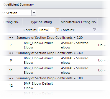
Example
of setting filter criteria in Type of Fitting, Contains: "Elbow"
Note: When the
filter is set, the filter icon
changes to
 .
|